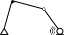
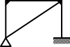
The following three relationships are used to solve different types of structural mechanics problems.
Relationship
Description
Equilibrium つり合い
Relationship between forces and stresses
Based on Newton's laws of motion: the sum of all forces acting on a structure at rest is zero.
Constitutive Relationships 構成則
Relationship between stress and strain
Based on the element's material properties and how it reacts to forces. A key example is Hooke's law, which describes linear-elastic material behavior.
Compatibility 適合
Relationship between strain and displacement
Describes geometry of deformation such that there is no rupture or overlapping of the material.
On the First Class Architect exam, you will need to be able to use the equations of equilibrium. You will also need to understand how to leverage compatibility and constitutive relationships, although you won't necessarily need to use formal equations, etc.
Constitutive Relationships
As mentioned above, the typical example of a constitutive relationship is Hooke's law: \(F=kx\). This is used to describe spring stiffness and is commonly used, e.g. axial stiffness: \(k=\frac{AE}{L}\). Another form of this same law is well known to engineers and describes the elastic stress-strain relationships: \(\sigma=E\epsilon\) or \(\gamma=G\tau\).
Continuity
You don't need to set up continuum equations, but you do need to identify basic contintuity conditions, i.e., displacement or slope continuity. Example:
A beam with an internal hinge: the deflection at the left and right side of the hinge is the same (deflection continuity)
Lateral translation of the joint between a beam and column of a sway frame requires the connected ends of the beam and column to move the same distance (translational continuity)
The angle between a beam and column must be preserved in a rigid joint (rotational continuity)
Positive Convention
It's important to use a consistent convention for positive forces and moments. The tricky part is that these mean different things, depending on whether you're looking at externally applied forces or internal stresses.
External Forces
For external forces, typically forces acting upwards and rightwards are positive. The US uses the right-hand-rule (RHR), which dictates that positive moments spin counter-clockwise (CCW). In Japan, it's common to defined positive applied moments as spinning clockwise (CW), which is the opposite of the RHR.
Internal Forces
Both countries use the same convention for internal forces:
Positive bending causes upward (smiley face) curvature. However, it's common in Japan to draw the moment diagram on the tension face of the member (which is mathematically the negative moment side, but this is convention for practical reasons in concrete design)
Positive shear causes a square to rack such that the left side raises, and the right side lowers, i.e. the shear couple on the sides creates a CW rotation (while the top and bottom create a CCW rotation)
Positive axial force causes elongation - this is tension. Compression, which causes axial shortening, is considered negative
Equilibrium
Structures in equilibrium satisfy the following three expressions, regardless of the point of reference.
Equations of Equilibrium
$$\sum F_X=0$$
$$\sum F_Y=0$$
$$\sum M=0$$
NOTE: Setting up the equations of equilibrium is a critical step in solving many structural analysis and free-body diagram problems.
Supports and Joints
External Supports
There are four main types of boundary conditions, illustrated in the table below. Typically, the reactions at supports are thought of in terms of a global frame of reference: Fx, Fy and M.
Boundary Conditions
Free
Roller
Pin
Fixed
No reactions
1 reaction
2 reactions
3 reactions
Internal Joints
There are several types of internal joints, which are different releases (degrees of freedom) for forces and moments acting within the structure.
Types of Internal Joints
Rigid
Pin
Axial Slider
Shear Slider
No releases
Moment release
Axial release
Shear release
Stability of Structures
Types of Structures
Unstable 不安定
Stable 安定
Determinant 静定
Indeterminant 不静定
Unstable structures that do not satisfy equilibrium equations.
Stable structures that can be solved with only equilibrium equations.
Stable structures that require compatibility or constitutive equations in addition to equalibrium equations.
There are several methods for rapidly assessing whether a simple 2D structure is unstable, determinant or indeterminant.
Japanese Method
The following equation is the commonly used in Japan, although it generates the same results as the alternative below.
\(m<0\) (Unstable)
$$m=n+s+r-2k$$
\(m=0\) (Determinant)
\(m>0\) (Indeterminant)
The defintion of each of these variables are as follows:
n = number of support reactions
s = number of member segments
r = number of rigid connections between members
k = total number of nodes (supports and internal joints, rigid or otherwise)
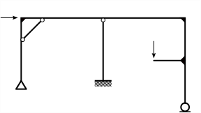
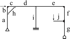
Example Frame
Example Frame
NOTE: the number of support reactions (n) is the sum of reactions at each individual support, based on the boudnary conditions. Refer to External Supports above.
Counting Nodes (k)
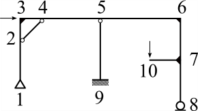
The illustration belows shows the example frame with all the nodes numbered. Nodes are the supports, joints and free-ends of members. Think of them as the dots you'd first have to draw, then connect with lines, to illustrate the structure.
Frame with Nodes Labeled
Counting Members Segments (s)
In this method, rather than counting physical members, you must count the number of segments between the nodes. This is why it's helpful to count the nodes first. For example, the three members a-b, c-d-e and f-g are single physical elements in reality, but count as seven segments in this example.
Frame with Members Labeled
Counting rigid connections (r)
The figure shows a joint with four members (s=4) framing into it. In this case, one of the members is pinned at the joint, the others are rigidly connected. In this case r = 2 because the the maximum number of rigid joints at a node is the number of members framing into it minus 1. Another way to think of it: \(r_{joint}=s_{joint}-pins_{joint}-1\).
Four-way connection
The same four-way connection with no pins would have r = 3.
Example Conclusion
Totalling up each of these components gives us the value m:
n = 6 (pin = 2, fixed = 3, roller = 1)
s = 10
r = 7 (joints 2 through 6 count as 1 each; joint 7 counts as 2)
k = 10 (3 supports, 1 free end, and 6 internal joints)
$$m=n+s+r-2k=6+10+7-2(10)=3$$
Since m > 0, it's clear the structure is indeterminant. In this case it's indeterminant to the third degree, which means we'll need to use equations of compatibility and/or the constitutive relationships in addition to equilibrium to analyze this structure.
For the purposes of the First Class Architecture exam, you'll only need to rapidly assess whether a frame is unstable, determinant or indeterminant. The degree and force analysis are generally not required.
Alternative Method
In North America and Europe, the following method is used. It is very similar, but groups the equalibrium equations slightly differently.
\(d<0\) (Unstable)
$$d=3m+r-3j-c$$
\(d=0\) (Determinant)
\(d>0\) (Indeterminant)
The defintion of each of these variables are as follows:
m = number of member segments)
r = number support reactions
j = number of nodes (supports and internal joints, rigid or otherwise)
c = number of internal releases
In this case the coefficient of 3 on members and joints comes from the fact that equalibrium satisifies three equations for each member and joint.
Which ever method is easier to remember is completely fine. They both yield the same results everytime.
Example Conclusion
Extending the example from above and summing for d:
m = 10 (member segments, same as above, s = 10)
r = 6 (support reactions, same as above, n = 6)
j = 10 (nodes, same as above, k = 10)
c = 3 (internal pins)
$$d=3m+r-3j-c=3(10)+6-3(10)-3=3$$
This demonstrates that the two approaches yeild the same results.
NOTE: Several quantities in both methods are the same, but with different coefficient letters: m (US) = s (Japan), r (US) = n (Japan), j (US) = k (Japan). The key difference is the US method totals internal hinge quantity (c), while the Japanese approach totals the internal rigid joints (r).